
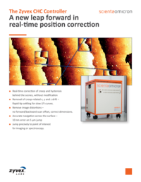
CHC Controller
A New Leap Forward in Real-Time Position Correction
- Real-time correction of creep and hysteresis behind the scenes, without modification
- Removal of creep-related x, y and z drifts - Rapid tip settling for slow I/V curves
- Remove image distortions - no forward/backword scan offset, correct dimensions
- Accurate navigation across the surface - 10 nm error on 5 µm jump
- Jump precisely to point of interest for imaging or spectroscopy
The ZyVector STM control system from Zyvex Labs uses live position correction to enable atomic-precision STM lithography. Now the same live position correction technology is brought to STM microscopy and spectroscopy users, enabling fast settling times after large movements in xy and z, and precise motion across the surface, landing and remaining at the desired location.
The Zyvex Smart Positioning System is seamlessly integrated with the Scienta Omicron MATRIX control system, making it the only commercial STM system with this capability.
What are creep and hysteresis?
Standard piezo actuators exhibit two types of position error:
1) creep which is a time-dependent error, whereby the last 10 % of any motion does not happen instantaneously, but occurs over tens or hundreds of seconds
and
2) hysteresis which is a position-dependent error; if the tip moves away from zero, and then back again, the tip will not return to the original location. The Zyvex Smart Positioning System adjusts the voltages delivered to the piezo actuators in order to correct these errors in real time, giving accurate and precise tip positioning. Corrections are applied to all four quadrants of the piezo tube, and therefore motions in x, y and z are all corrected.
Creep Correction
For any motion, the piezo moves about 90 % of the distance instantaneously, and the last 10 % slowly as creep. Therefore, by overshooting the applied voltage, the piezo will move to the desired location instantaneously. Then the overshoot voltage is reduced over time following the calibrated creep curve, so that the tip remains at the desired location.
Hysteresis Correction
When the piezo moves away from zero, it moves further than expected given the applied voltage. When it returns, it does not return to the starting point. Hysteresis correction applies voltage over- or under-correction to compensate for these position errors.
More Information
Correcting Z Creep During Landing
The z voltage is plotted for uncorrected creep, and with creep correction applied. With uncorrected creep, the z voltage is still changing quickly after 30s. With the creep correction there is almost zero motion after less than 10s (residual z motion at 20s is about 4 nm/h). This allows for much shorter settling times after movement before performing spectroscopy.
Remove Image Distortions – No Forward/Backward Scan Offset

Without creep correction, there is an offset between Forward and Backward scans of 3.6 Å (1/2 a dimer row for the Si(100) surface). With creep correction applied, the offset is zero. Without fast creep correction, the forward/reverse offset means the tip is never where you think it is. Fast creep during scanning also affects the measured lattice parameter, so metrology of surface features will be incorrect.
How it Works

Piezo creep results in an undershoot of real position vs. desired position. The actual position is path and velocity- dependent. Real-time creep correction is therefore necessary to compensate for each motion as it occurs. A voltage overshoot is applied to correct the position undershoot. The applied voltage is set to decay with time to match the expected creep, keeping the tip at the correct real position. The creep must be calibrated for each scanner, but is around 10 % of the motion. The CHC box receives the piezo voltages from the MATRIX controller, modifies them to correct for creep and hysteresis, and then passes the corrected voltages on to the MATRIX piezo drivers. In this way, the corrections are achieved without any required modification of the MATRIX system.
Downloads
Zyvex CHC Controller
Scienta Omicron and Zyvex Labs announce a new leap forward in STM design; real- time position correction. The ZyVector STM control system from Zyvex Labs uses live position correction to enable atomic-precision STM lithography. Now the same live position correction technology is brought to the Matrix STM control system for microscopy and spectroscopy users, enabling fast settling times after large movements in x, y and z, and precise motion across the surface, landing and remaining at the desired location.